ShieldSigner / build & use0.0.19-dev
01 / 22The build~25s

Building ShieldSigner with AI

From schematic to printable enclosure, driven by code.

  • PCB → assembly → enclosure
  • Fast iteration. Explicit evidence.
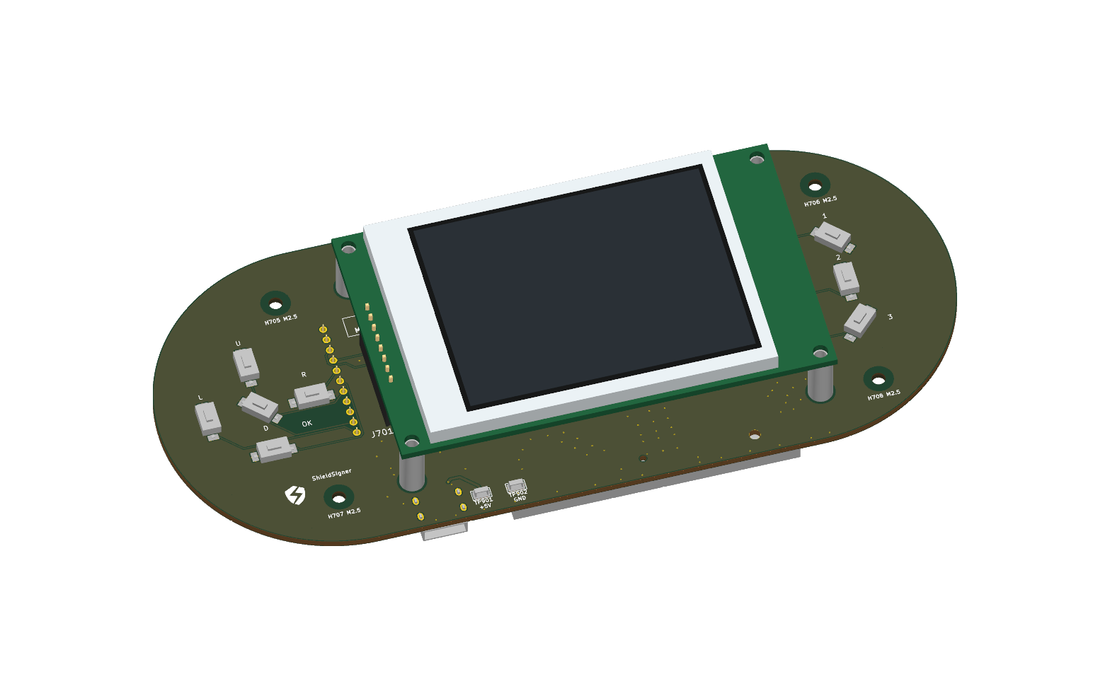
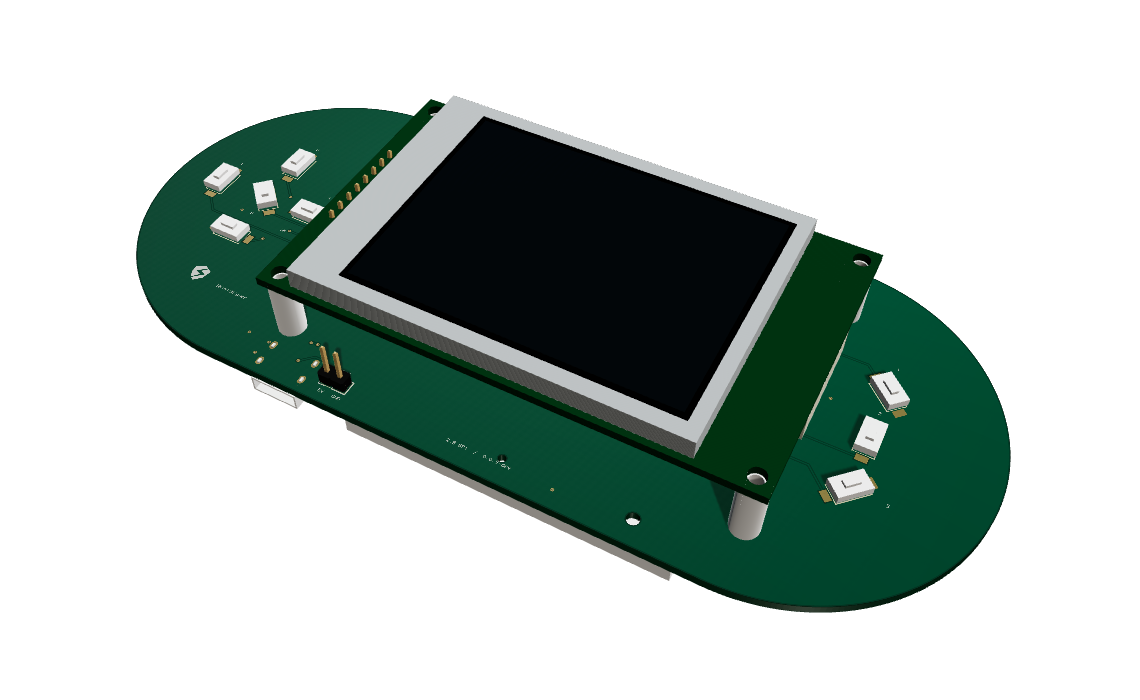
Rendered ShieldSigner pill carrier assembly with its large LCD and controls
Digital carrier assembly · physical first article pending
Sources & further reading
#intro
Presenter notes

This is a builder story: using AI to move between schematics, source, supplier drawings and mechanical models. The project is a development prototype, not a claim that a home-built signer is safer than commercial products. The main story is the PCB and 3D iteration; the camera and LVGL work show what happened when the hardware met software. Credit SeedSigner, ShieldSigner and their contributors throughout.

02 / 22Understand the system~65s

What does a Bitcoin signer do?

Review a proposed transaction. Approve a signature.

  • The coordinator prepares the transaction
  • The signer displays the transaction details, then signs it after you approve
  • The coordinator broadcasts the result
  1. COORDINATOR → QR → SIGNERProposed transactionPSBT: transaction + signing metadata
  2. HUMAN REVIEWCheck outputs and feesKeys authorize spending; coins stay on the network
  3. SIGNER → QR → COORDINATORSigned transaction dataCollect signatures, finalize and broadcast
Sources & further reading
#signer
Presenter notes

Start without assuming Bitcoin expertise. Coins are recorded on the network; the device holds or temporarily reconstructs keys that authorize spending. PSBT means partially signed Bitcoin transaction: a package of transaction data and signing metadata. The coordinator can prepare a proposal without having the private keys. The signer must show meaningful outputs and fees for the human to verify. SeedSigner exchanges this information through QR codes; the coordinator then collects signatures and broadcasts. A QR air gap changes the transport, but untrusted inputs and misleading transaction information still need validation. A seed is a backup secret, not a picture to project during this talk.

03 / 22Understand the system~40s

From SeedSigner to ShieldSigner

What we inherited, adapted and built.

  • SeedSigner: Python signing application
  • ShieldSigner: Luckfox and smartcard adaptations
  • This project: carrier, case and integration
  1. FOUNDATIONSeedSignerPython app · QR exchange · Raspberry Pi ecosystem
  2. HARDWARE ADAPTATIONShieldSignerLuckfox platform · smartcard integration
  3. THIS BUILDCarrier + case + firmwareReuse upstream signing logic; improve the surrounding interfaces
Presenter notes

Credit the lineage before discussing AI. SeedSigner provides the original application, QR workflow and Raspberry Pi hardware ecosystem. ShieldSigner adapts the project toward Luckfox and smartcards. Our work builds on those contributors, the pinned application and kdmukai’s portable LVGL screens. The custom 2.8-inch pill carrier and enclosure are new design work; the demonstrated device is the existing 240×240 bench. Distinguish reuse, adaptation and original integration. AI helped navigate these boundaries and build repeatable tools; it did not invent the Bitcoin protocol or replace the upstream signing implementation.

04 / 22Why build?~35s

Where trust enters the system

Keys, software, hardware, distribution and recovery.

  • Seed generation
  • Device + distribution
  • Recovery + verification
  1. 01Generate the secretEntropy & implementation
  2. 02Receive the deviceHardware & distribution
  3. 03Approve a transactionDisplay & verification
  4. 04Recover the walletBackups & policy
Sources & further reading
#trust
Presenter notes

Before showing CAD, explain the motivation: understand the interfaces and reduce opaque assumptions. Firmware, entropy generation, the device, reseller handling, coordinator and backups are different trust boundaries. Open source helps inspection; it does not prove a particular binary, assembled board or recovery procedure is correct. Building this prototype teaches those boundaries rather than removing them.

05 / 22Why build?~40s

Two hardware-wallet incidents

Different failures in seed generation and device distribution.

  • July: weakened seed generation
  • October: reseller hardware implants
  • Updating ≠ repairing an old seed

COLDCARD

Weakened seed generation

Firmware / entropy boundary

Ledger reseller incident

Physical implants capture recovery phrases

Hardware / distribution boundary

Different failure paths. Primary incident sources below.

Presenter notes

Coinkite published its seed-generation advisory on July 30, 2026. Affected firmware produced weakened seeds; its current status page distinguishes fixed releases and explains that updating does not repair an already affected seed. Check the official guidance rather than a model-name shortcut. Ledger’s October 15 response describes localized reseller-distribution implants that captured recovery phrases during setup. Ledger says its chip, OS and servers were not compromised. These illustrate distinct failure paths, not proof that either whole product family or our prototype is categorically unsafe or safe. Do not state unverified aggregate theft figures.

06 / 22Why build?~45s

Multi-vendor multisig

An experimental signer can participate without controlling the wallet.

  • Spread trust across vendors and implementations
  • One compromised signer cannot spend on its own
  • Keep a recovery path without the experimental device

ONE WALLET · SEPARATE VENDORS AND KEYS

ESTABLISHEDVendor AIndependent key and implementation
ESTABLISHEDVendor BDifferent vendor and signing stack
EXPERIMENTALShieldSignerOne key; never sole authority
Limit how much any one signer must be trusted.

Use the experimental signer when available. Retain a tested signing path through the other two.

Illustrative 2-of-3 setup. Independent seeds, verified wallet policy and addresses, descriptor backup and recovery testing remain essential. Different brands can share underlying code.

Presenter notes

The audience already understands the threshold; spend this slide on why the signers should differ. A hypothetical 2-of-3 arrangement can combine two established signers from different vendors with an experimental ShieldSigner, each holding an independently generated key. If only the experimental key is exposed, it cannot authorize a spend. If the prototype is unavailable, the other two can still sign, provided they remain available and the wallet configuration is retained. Compared with placing sole authority in that experimental device, this limits the consequences of its failure or compromise. It is not a blanket claim that any multisig arrangement is safer than every single-signer setup: correlated dependencies, compromised wallet setup, misleading addresses, operational mistakes and backup loss still matter. Verify the policy and receive/change addresses using independently trusted devices, review transactions there, retain the descriptor and test recovery. Vendor names alone do not establish implementation independence; the following library slide explains shared dependencies. This is an architecture argument, not a report of a qualified or funded ShieldSigner deployment. The next step for this prototype is practice with disposable keys and every signing pair, not assigning it sole custody.

07 / 22Understand the system~110s

The SeedSigner software stack

How the application, libraries, UI and drivers fit together.

  • Application policy stays above the libraries
  • Bitcoin parsing and cryptography are different layers
  • UI, QR and drivers have their own interfaces
SeedSigner Controller · Views · modelsReview policy · navigation · signing orchestration

Coordinates navigation, wallet state, transaction review and signing.

Calls the Bitcoin library, QR handlers and screen services to carry out the user’s chosen workflow.

Open a block to see what it does and how it connects.

↕ Bitcoin data → signatures

embitPSBT · descriptors · derived keys
What it does
Provides Bitcoin transaction, PSBT, descriptor and key-handling functions.
How it connects
The application calls embit to interpret Bitcoin data, derive keys and create signatures.
Cryptographic backendCurve operations · hashes
What it does
Performs the low-level elliptic-curve operations used for public keys and signatures.
How it connects
embit calls a cryptographic backend selected for its runtime environment.

↕ Camera → application data

QR and animated formatsFrames → bytes → complete payload
What it does
Reads QR codes and assembles animated sequences into a complete payload.
How it connects
Camera frames go to the QR decoder; decoded bytes go to the application’s format handlers.
Camera acquisitionSensor / ISP → grayscale frames
What it does
Captures images for the preview and QR scanning.
How it connects
Sensor and ISP drivers provide frames to the camera service, which passes them to the preview and QR decoder.

↕ Screen ↔ user decisions

Screen renderingScreen contracts ↔ typed events
What it does
Draws menus, transaction details and QR codes.
How it connects
The application sends screen content to the renderer and receives selections and actions in return.
Display and input I/OPixels · SPI · GPIO events
What it does
Sends pixels to the display and reads button presses.
How it connects
Display drivers use SPI and control GPIOs; input drivers turn switch signals into application events.
CPython + Linux + board-specific drivers

CPython executes the application. Linux manages processes, memory and access to devices.

Board-specific drivers connect the software services to the camera, display and GPIO hardware.

Parallel branches serve the application. The cryptographic backend sits beneath the Bitcoin library; QR decoding does not replace transaction parsing.

Presenter notes

Follow the three branches from the application: Bitcoin data and signing, camera and QR input, and screen rendering and user input. embit handles Bitcoin structures and operations; its cryptographic backend performs lower-level curve operations. QR readers supply decoded data to the application. Linux and board drivers support all hardware-facing services. The diagram describes responsibilities and connections; the dedicated camera and UI sections explain our implementations.

08 / 22Understand the system~90s

Bitcoin libraries and shared dependencies

embit, rust-bitcoin and libwally take different approaches.

  • embit · rust-bitcoin · libwally
  • APIs and supported features differ
  • Shared dependencies need explicit review
Python / MicroPython

embit

Embedded Bitcoin data, keys and signing workflows

SeedSigner dependency
Rust

rust-bitcoin

Bitcoin types, parsing and serialization

Alternative integration to investigate
C + bindings

libwally

Wallet primitives across languages

Alternative integration to investigate
Trace the cryptographic backend ↓

Separate APIs can converge on libsecp256k1-based code. Inspect the actual versions, build options and loaded backend.

Examples of library ecosystems, not drop-in replacements or proof of independent implementations.

Presenter notes

Explain the distinction between a Bitcoin library and a primitive cryptography implementation. embit targets embedded Python/MicroPython applications. rust-bitcoin provides Rust Bitcoin types and serialization. libwally offers C wallet primitives and bindings. These are examples to compare, not three installed alternatives in this firmware and not drop-in replacements. embit can select a libsecp256k1-based backend; libwally includes libsecp sources, and the Rust ecosystem also has secp256k1 bindings. Different languages therefore do not establish independent cryptographic ancestry. Reuse can concentrate expert review and fixes; independent implementations can reduce some common failure modes but require serious testing. An adapter should compare descriptor/address derivation, transaction round trips, signing preimages, valid signatures, and malformed or unsupported inputs. Matching test vectors do not prove complete independence or correctness.

09 / 22Understand the system~110s

The hardware and its connections

From the Raspberry Pi reference build to our Luckfox carrier.

  • A connector shape is not a pinout
  • Bus, voltage and geometry must agree
  • A new processor is a board + software port

SeedSigner reference: Pi Zero · 240×240 LCD/button HAT · Pi-compatible camera

Luckfox Mini · Linux compute moduleOur adaptation: Luckfox Mini + microSD boot on a custom 160 × 70 mm carrier

Runs Linux and the signing application, booting from microSD.

Connects to the display, controls, smartcard interface and power through the carrier, and to the camera through its dedicated camera connector.

Open a block to see what it does and how it connects.

CameraModule camera connector → sensor / ISP
What it does
Captures images of QR codes.
How it connects
The SC3336 camera connects to the Luckfox module’s dedicated camera connector and feeds its image-processing pipeline.
DisplaySPI + reset / data-command · 3.3 V logic
What it does
Shows menus, transaction details and QR codes.
How it connects
The eight-pin HOTHMI module receives pixels over SPI, with GPIO signals for command selection and reset.
ControlsGPIO inputs with pull-ups → switches
What it does
Lets the user navigate, select and confirm actions.
How it connects
Joystick directions, joystick press and three keys connect to GPIO inputs with pull-ups.
SmartcardUART ↔ SEC1210 ↔ card contacts
What it does
Provides a contact interface for supported smartcards.
How it connects
The Luckfox communicates over UART with the SEC1210, which handles card power, clock, reset and data through the socket.
PowerUSB-C / optional header → 5 V rail
What it does
Supplies power to the compute module and carrier electronics.
How it connects
USB-C or the two-pin header supplies 5 V; a dedicated regulator supplies the display’s 3.3 V rail. USB-C is power-only.
Carrier and enclosureLands · headers · mounts · clearances
What it does
Routes the electrical connections and holds the assembly in place.
How it connects
PCB headers join the modules; enclosure mounts and spacers position the board, display, controls and camera.

These are functional connections, not a wiring diagram. Camera connects to the compute module; the carrier routes the display, controls, power and card interface.

Presenter notes

Follow each connection from the Luckfox Mini. The camera uses the module camera connector. The display uses SPI and control GPIOs; the switches use GPIO inputs. UART connects the SEC1210 smartcard controller to the host, while the controller manages card contacts. The carrier routes power and signals, and the enclosure positions the parts. USB-C is a power input. Use one 5 V power source at a time.

10 / 22Understand the system~55s

Replacing hardware and software

What can change, and what needs to stay compatible.

  • LVGL: a demonstrated screen boundary
  • New LCD: driver + wiring + mechanical work
  • New Bitcoin library: semantic compatibility work
  1. DEMONSTRATED · BENCHPython screens → LVGLKeep screen content, events and confirmation semantics
  2. DESIGN + HARDWARE QUALIFICATIONSmall LCD → 2.8-inch moduleAdapt driver, pinout, power and mounting
  3. INTEGRATION EXERCISEembit → another libraryCompare derivation, parsing, sighashes and invalid inputs
Presenter notes

Use these three contrasting examples. The LVGL migration demonstrates a replacement through a defined screen/event protocol while preserving the original application’s decisions. A new LCD has a familiar SPI bus but can differ in numbering, controller initialization, dimensions and electrical requirements. Replacing embit is deeper: the adapter must preserve wallet semantics, not just function names. The capability diagram shows possibilities; it does not claim every block has been replaced. Distinguish the working bench, native software checks and unqualified pill first article throughout.

11 / 22AI + hardware~65s

How I worked with AI

I set the direction. AI helped turn it into code, tools and working hardware.

  • Start with a concrete change
  • Keep the result easy to inspect
  • Turn repeated work into tools
“Add the denver.space logo to the PCB silkscreen.”
  1. Set the constraintsUse the official artwork. Keep copper, components and the board outline unchanged.
  2. Investigate and implementAI reads the existing design and writes a script to generate native KiCad artwork.
  3. Inspect and correctI review the rendered board, give feedback on placement and legibility, and ask for another pass.
  4. Check and keep the toolCompare the electrical design, run the board checks and save the generator for the next revision.

One request leaves behind a reusable silkscreen generator. The same workflow applies to PCB edits, case dimensions and firmware—with physical tests for fit and behavior.

Presenter notes

My role was to choose the goals, constraints and tradeoffs, then inspect the results and test the hardware. AI helped read repositories and datasheets, trace connections, edit PCB and enclosure files, port software and write the tools to repeat those edits. The silkscreen example is small enough to follow end to end: start with official artwork, generate native KiCad polygons, render the board and check that the electrical design stayed unchanged. The same pattern scales to moving components, changing case dimensions and iterating camera software. Independent research and review can run in parallel; changes still need clear ownership. When the process wandered, a smaller task and an explicit next test brought it back. Each useful iteration left behind source, a repeatable command and evidence I could review. On the camera and UI, that included running the result on the real board.

12 / 22AI + hardware~75s

Designing the carrier PCB

AI helped connect datasheet research, electrical review and repeatable manufacturing outputs.

  • Read the datasheets for every major IC and module
  • Match KiCad symbol pins and footprint pads to the real part
  • Check voltage domains, signal functions and connector order
  • Generate matched BOM, placement, Gerber and drill files
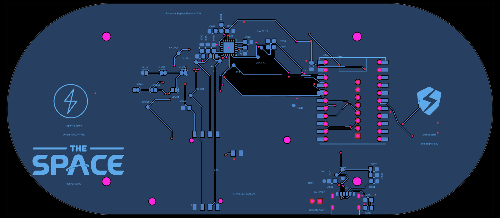
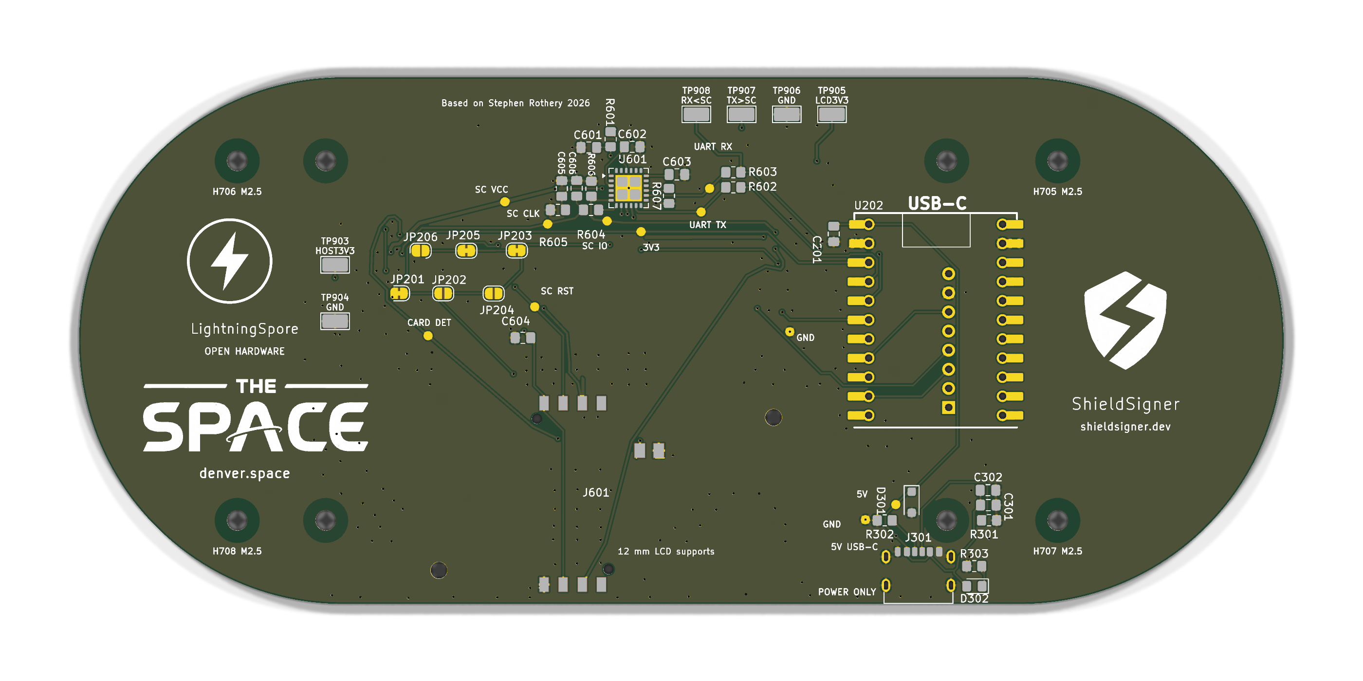
Straight-on main ShieldSigner carrier PCB top view with routing and silkscreen
Native KiCad render · 43 fitted SMT placements / 18 SKUs

Datasheets → pin and pad audit → checked design → manufacturing package. Scripted edits and exports make revisions repeatable and keep the parts list and placement files tied to the same PCB revision.

Presenter notes

Start by collecting the manufacturer datasheets and mechanical drawings for the major components: the Luckfox module, LCD, camera, smartcard controller, regulators and connectors. AI helps extract pin tables, supply limits, interface requirements and recommended support circuitry into a reviewable component guide. Check each KiCad symbol pin number, name and electrical type against the datasheet, then follow it through the footprint pad and board net to the physical part. Check connector viewing direction and pin-one orientation as well as signal names. This caught concrete issues: SEC1210 power-output pin types needed correcting, and its output decoupling changed from 100 nF to 1 µF to match the datasheet recommendation. Review voltage domains, module pinmux, bus signals and power paths together. Use scripts for repeatable native edits, then run schematic ERC, PCB DRC, connectivity and schematic-to-PCB parity checks. Generate the BOM with readable values, manufacturer part numbers and supplier references, the CPL pick-and-place file, and Gerbers and drill files from the same revision. Keep DNP choices and assembly rotations explicit. The main review kit has 35 fitted SMT parts across 17 supplier SKUs. Automated checks and a manufacturing package still require a physical first article to qualify assembly, fit and powered operation.

13 / 22AI + hardware~65s

Porting the board to tscircuit

TypeScript could make tscircuit a more AI-native PCB tool in the future. I still prefer KiCad today.

  • Components and connections expressed in TypeScript
  • Seven sheets, editable silk and 3D models
  • Check footprints and electrical connections
We checked that the tscircuit version preserved the component footprints and electrical connections. See the comparison checks ↗

An early visual port became a source-authored circuit. Both representations remain useful; the new routing is not hardware-qualified.

Presenter notes

Show a concrete AI iteration: the first port reproduced appearance using imported native geometry and copper, which was useful for comparison but not idiomatic source authoring. The rebuilt version uses semantic tscircuit primitives, functional sheets, local footprints and assets, and fresh built-in autorouting. Compare 190 physical lands within 0.005 mm and electrical partitions in both directions, then run placement, shorts and routing-style checks. That establishes specific software evidence, not hardware qualification or equal routed copper. This example demonstrates tool translation; KiCad remains the native reference and preferred workflow. There are recorded upstream core/schema incompatibilities and unresolved generic-header part-selection warnings; do not claim a perfect exporter or production-ready new layout. The longer-term possibility is a more AI-native PCB workflow: components, connections and layout are expressed in TypeScript, giving AI familiar source code to read, edit and review with normal diffs. That is a promising direction rather than a claim that tscircuit is already a more mature PCB editor.

14 / 22AI + hardware~75s

Designing the enclosure in OpenSCAD

OpenSCAD creates 3D models from code: shapes, dimensions and operations.

  • Combine shapes; subtract holes and openings
  • Use parameters for walls, clearances and mounting posts
  • Change the code, preview the model, export parts to print
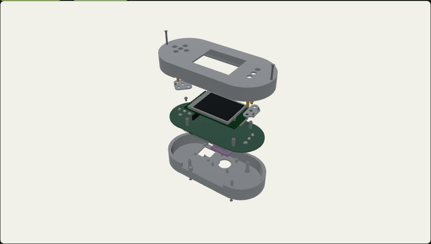
Exploded digital case assembly with carrier, display and enclosure parts
Digital assembly · adjustable camera/ribbon envelopes

The enclosure is a program: edit its dimensions and regenerate the geometry. Next, inspect how the PCB, modules and shell fit together.

Show the case parameters
button_switch_height = 2.7;
button_gap = 0.15;
button_stroke = 0.40;
wall = 2.4;
outer_size = [176,82];

Millimetres. Actual OpenSCAD source; change parameters, regenerate parts, then check fit.

Presenter notes

OpenSCAD is a code-based 3D CAD tool. You describe solids such as boxes and cylinders, position them with transforms, and combine or subtract them. A case wall can begin as an outer box with an inner box removed; another cut creates a connector opening. Variables and reusable modules control dimensions and repeated features such as screw posts. Preview the model as you edit, then render and export a mesh for slicing and printing. This gives AI concrete source code to work with and gives us readable diffs and repeatable geometry. For this project, the PCB supplies the outline, mounting holes and component positions; module drawings supply the remaining dimensions. Adjust the case around those constraints, then inspect the complete assembly in the next section. Camera and ribbon models are adjustable envelopes and screw threads are omitted.

15 / 22AI + hardware~70s

Does the complete assembly fit?

Bring the PCB, modules and enclosure together to inspect the fit.

  • Inspect header heights and mating depths
  • Look for collisions and blocked connectors
  • Use the model to plan a printed fit test

3D loads when this section comes into view.
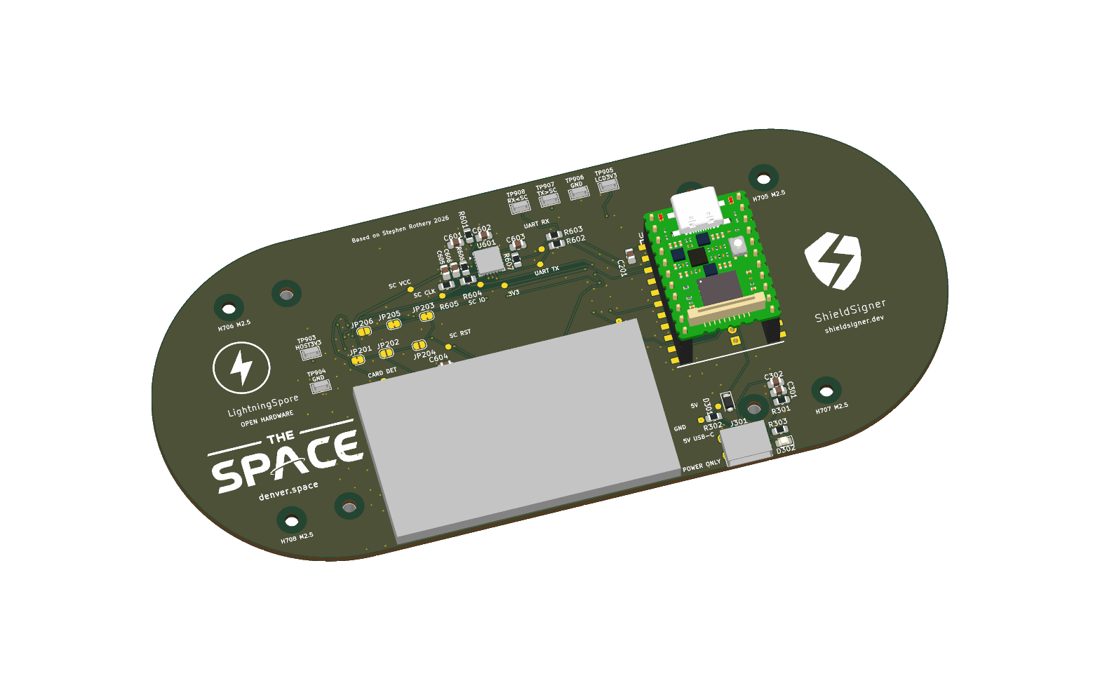
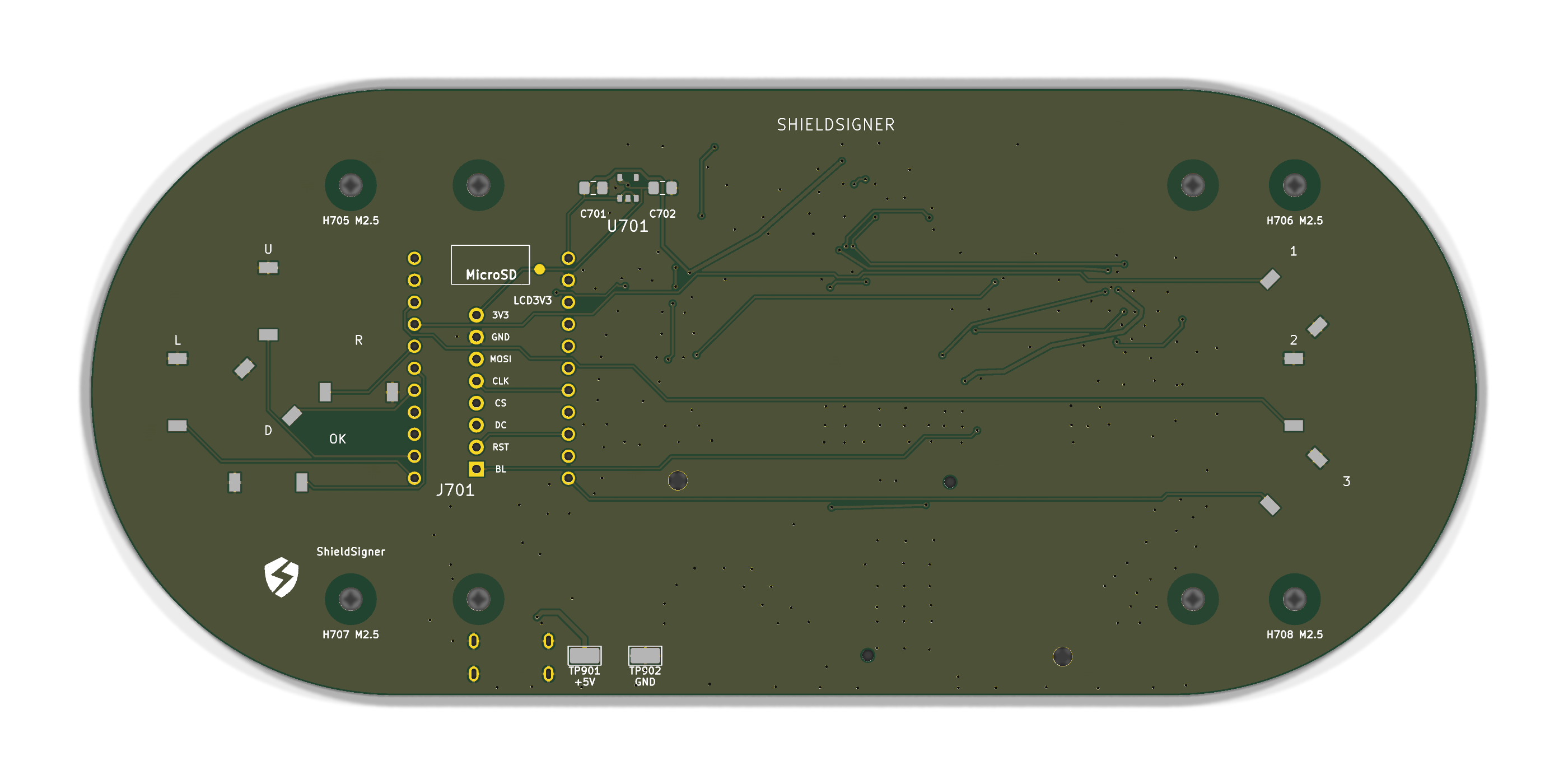
Rendered carrier back showing the smartcard socket, power connector and module mounting

Nominal stack: 35.52 mm. Purchased header tolerances and physical fit still need checking. Download the PCB assembly ↗

Presenter notes

Now inspect the result of the PCB and enclosure work together. Rotate the assembled model, open the exploded view, and use PCB assembly and transparent case-fit modes to inspect interfaces. Check that display and Luckfox headers mate at the intended depth, spacers support the stack, and connectors and buttons remain accessible. Look at camera placement and cable clearance. If a header makes the case too thick or an opening is blocked, return to the PCB or case parameters and regenerate. A digital model helps identify problems before printing; a printed fit sample and real purchased components are still needed to verify tolerances. Finish the hardware story here, then move on to the camera and UI software.

16 / 22AI + firmware~50s

Controlling the camera in Rust

AI helped investigate the vendor interfaces and build a camera service we could inspect and change.

  • Trace sensor and image-processing controls
  • Implement exposure, white balance and frame delivery
  • Inspect captures and test each change on hardware
  1. UNDERSTANDCamera + image processingTrace the vendor interfaces for sensor settings and frame delivery.
  2. IMPLEMENTRust camera serviceControl exposure and white balance through existing Linux drivers.
  3. TEST + ITERATEInspect real capturesUse the hardware to check the result of each change.

This service replaces the RKAIQ userspace path. It still uses Linux drivers and the Luckfox SDK. Next: turn camera frames into QR data.

Presenter notes

Bridge from physical fit to software: even with the camera connected, the application needs correctly exposed frames it can decode. AI helped investigate the vendor interfaces, implement a Rust camera service and iterate against images and QR tests on the real camera. The useful loop was inspect a capture, identify a specific problem, change the implementation and test again. Exposure, white balance and the frame path mattered more than a successful build. The service uses existing Linux sensor and ISP drivers without calling the RKAIQ userspace library; this is not complete RKAIQ parity or a Linux-free design. ZXing-C++ is the existing QR decoder. It consumes grayscale frames directly, avoiding an unnecessary JPEG conversion, and returns bytes for the Python application to assemble and interpret. The next section addresses how the application displays its interface. Keep QR decoder selection for the next slide: this section ends at delivering usable camera frames.

17 / 22AI + firmware~55s

Replacing ZBar with ZXing-C++

Another AI-assisted library swap: preserve the decoded bytes, change the reader.

  • Compare readers on identical camera frames
  • Adapt the grayscale input and binary-byte output
  • Keep animated QR assembly in the application
ORIGINAL READERZBar through pyzbar

Camera image → Python binding → decoded QR bytes.

REPLACEMENT READERZXing-C++ native worker

Grayscale frame → decoder → the same application byte interface.

Recorded test: both pipelines read 24/24 attempts on four saved camera frames. ZBar needed preprocessing; ZXing read the raw frames. All nine binary-payload fixtures passed for each reader.

Presenter notes

The existing app used ZBar through pyzbar. AI helped build decoder comparisons, investigate preprocessing, cross-compile ZXing-C++ and connect the native worker to the app. The shared pipeline tried a raw frame, a center crop and finally local thresholding. On the same four saved VGA camera frames, repeated six times each, both pipelines reached 24/24 matching reads. ZXing succeeded on the raw frames; ZBar needed the final threshold stage. Median complete prototype pipeline time was 35.1 ms for ZXing and 174.8 ms for ZBar. This includes preprocessing, process startup and I/O, with capture stopped; it is not live app FPS or a universal decoder ranking. The final threshold helper uses ZXing’s HybridBinarizer, so the successful ZBar pipeline also depends on that preprocessing component. Binary fixtures passed 9/9 for each reader, including NUL and all 256 byte values. The adaptation must preserve bytes rather than force text decoding. Python continues to assemble animated QR formats and interpret application payloads. The QR algorithm itself was not rewritten in Rust.

18 / 22AI + firmware~50s

Moving the interface to LVGL

Build on Keith’s longstanding work bringing SeedSigner’s interface to LVGL for microcontrollers.

  • LVGL provides graphics and widgets for embedded devices
  • Adapt Keith’s screens to the Luckfox Linux platform
  • Use AI to integrate, test behavior and investigate memory
APPLICATIONPython decides what to show

Navigation, wallet state and transaction review.

DISPLAY + INPUTLVGL draws the interface

Native C/C++ screens receive content and return user actions.

Built on Keith’s (kdmukai) longstanding LVGL work for SeedSigner on microcontrollers. Our contribution: adapting and integrating it on Luckfox Linux.

Presenter notes

Keith (kdmukai) has longstanding work porting SeedSigner interfaces to LVGL for microcontrollers. Make that foundation explicit before describing our contribution. LVGL supplies embedded graphics and widgets. We adapted Keith’s screen work to the Luckfox Linux platform and connected it to the existing Python application. AI helped map screen contracts, integrate the native renderer, preserve input/navigation behavior, audit dependencies and measure memory. The Python Controller and models still manage application and wallet logic. The tested development image booted with usable menus and camera scanning on the standard bench hardware. Memory comparisons must account for the same workload and all processes, including Python, the camera, QR worker and renderer. Pillow still has still-image and entropy consumers. Credit SeedSigner, ShieldSigner and Keith’s portable screens; this is adaptation and integration built on their work. The next slide demonstrates those pieces together.

19 / 22Show it working~90s

Try the camera and interface together

A short demonstration on the working Luckfox bench device.

  • Navigate the LVGL menus with the buttons
  • Open the camera and scan a public test QR
  • Return to the menu and repeat the scan
  1. 01 · NAVIGATEUse the menusShow the display updating and the buttons responding.
  2. 02 · SCANRead a public test QRShow the camera preview and the application receiving the decoded result.
  3. 03 · REPEATLeave and reopen the scannerCheck the camera and UI working together through another cycle.

Working bench: Luckfox + standard 240×240 display/button board. The new 2.8-inch carrier is awaiting physical qualification.

Presenter notes

The PCB and enclosure have already been shown; use this section to demonstrate the firmware behavior just discussed. On the prepared Luckfox bench device, navigate the LVGL interface, enter camera scanning, scan a non-secret public test QR in a format the app supports, then leave and enter the scanner again. Explain what is visible rather than claiming broader wallet coverage from a QR scan. The bench uses the standard 240×240 display/button board; the new 2.8-inch carrier still needs first-article qualification. If the device is unavailable, explain the recorded test scope using the linked firmware status rather than presenting the case render as working hardware. Keep seeds, recovery phrases and private wallet data off the projector.

20 / 22What we learned~65s

What we have verified

Software checks, bench results and remaining carrier tests.

  • Native checks + provenance
  • Continuity + rails + actual pinmux
  • Tested bench ≠ qualified carrier
Native rear PCB view with The Space logo and denver.space silkscreen
Actual native PCB render · artwork revision 0.0.11
0protected PCB objects changedInspect the artwork-only comparison ↗
Presenter notes

The biggest concrete lesson: the working base-fork firmware drives GPIO56/57 as LCD outputs, while the carrier uses those nets for Left/Up buttons to ground. Pressing a button can ground a driven output. The carrier net map agrees with its intended carrier profile; rewiring it to mimic the bench would be the wrong response. The new carrier needs the carrier image, 10 MHz LCD clock, 320×240 settings and physical bring-up. Frozen-image hashes and packed checks establish exact artifacts, while first-article electrical/mechanical tests establish different facts. AI accelerated finding this mismatch; it did not exempt us from checking it.

21 / 22First article~30s

Estimated build cost: about $100

Earlier estimates, with shipping and other exclusions.

  • Earlier five-PCB quote basis
  • Modules + carrier + printed case
  • Shipping, tax, battery and card excluded
COMPLETE UNIT · PLANNING ESTIMATE~$100
Assembled carrier¹
$39.11
Luckfox Mini A + headers
$12
Camera
$13
2.8-inch LCD
$15.47
microSD allowance
~$10
Hardware + printed case allowance
~$8–13

¹ Historical five-board quote, per board. Shipping, tax, battery, smartcard, tools and labour excluded. Check current order gates.

Presenter notes

Present approximately $100 as the earlier project-level estimate, not a guaranteed landed per-unit price or a current supplier checkout. The old five-PCB quote and earlier component/module estimates have different dates and assumptions; do not silently divide a five-board assembly total into an independent one-off order price. Battery, smartcard, shipping and tax are outside this estimate. Stock, attrition, setup charges and spares can change the result; the current readiness guide records a socket sourcing gate. The point is learning and an affordable first article, not a production cost claim.

22 / 22Next~35s

Next: assemble and test the carrier

Check the real board, fit the case and verify the complete workflow.

  • Qualify the carrier first article
  • Practice recovery with disposable keys
  • Contribute a reproducible improvement
shieldsigner.devGet the source ↗

PCB · mechanical models · firmware · repeatable tools

Built on SeedSigner, ShieldSigner, kdmukai’s screen work, LVGL, Linux and Luckfox.

The Space — denver.space
Presenter notes

Close with the actual next step: one powered carrier first article with the correct profile, continuity/rail/button/display/camera checks, and a printed fit test. Real-wallet end-to-end acceptance remains pending. Invite review of a net, a footprint, a source guard, an enclosure clearance or a repeatable test rather than generic trust in the prototype. Thank SeedSigner, ShieldSigner, kdmukai/LVGL, Linux, Luckfox and the wider open-source contributors. Link the project and Denver.space. The useful artifact is not only a board: it is a workflow that makes the next question cheaper to answer.